Renzotech strikes back
07 May 2010Not dead yet!
I realized it’s been a long time since I last waggled my soldering iron and that I missed the chemical smell of melting tin. It’s been a way longer time since I last played with high voltage. That’s why I recently decided to keep my hands busy at doing… more productive affairs.
One of the experiences I’ve already have a shot at is to build a Tesla coil. A Renzotech one obviously. It has worked quite nicely but required some space to operate and due to the spark gap design.
I don’t have such space available nowadays. Moreover, the 6kV neon sign transformer is no more in my possession. I’ve also come to know that window bars make lousy earth grounds. That’s why I decided to try a smaller solid state design.
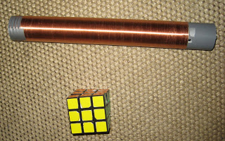
First step first, I need a coil for the secondary of my transformer. A small design wouldn’t require much enamel copper wire. This thing is quite expensive but is easy to find in ‘the nature’. Most old CRT screens actually have a coil around the screen for demagnetization purposes. You certainly have played with that. It’s fun since it makes the screen go all shaky for a few seconds, LOL.
Wiring the secondary was a tedious work. It took me more than 2 hours to complete 25cm (around 600 turns) around a plastic tube.
Now I have the coil, I need to know its inductance. Since I own an oscilloscope, I can do a remake of the old physics practial exercise: LC circuits! Didn’t know I was going to knowingly use that half-forgotten knowledge for a real and fun purpose.
This is the circuit I’ll use:
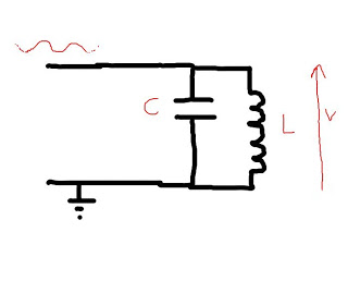
I only require a frequency variable generator (FVG) and Physics says that the amplitude V is max when the frequency is 1/(2 Pisqrt(LC)).
Well to be honest, I had to Google everything, and still I’m not so sure about the equation. I’ll gladly accept any correction.
I wanted at first to make my FVG with an Arduino. It would have been easy to put some code together to meet my needs since one can find PWM libraries. The main problem is that I just couldn’t find the damn little board (it was later revealed that it has been put away in some box with other similar devices instead of laying on my working table under tons of stuff as it should be). Another issue is that I don’t know how the circuit would behave with a square wave instead of a sinusoidal signal.
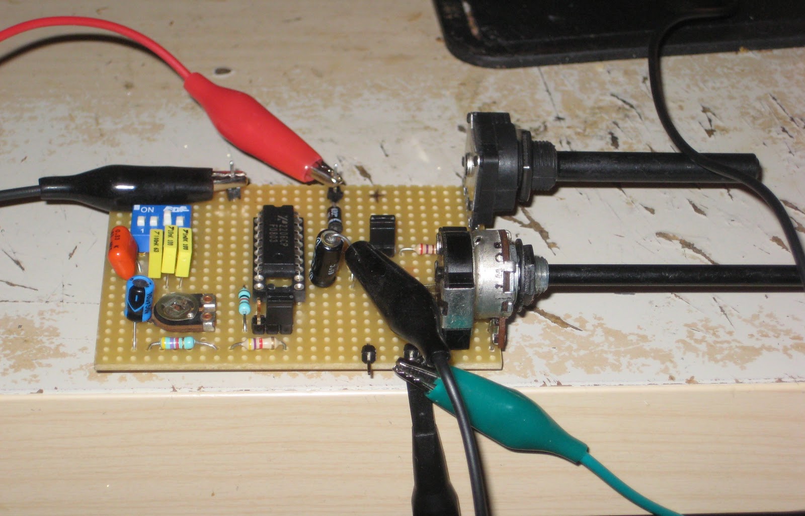
By the light (or darkness?) of those nifty issues, I go on building my own signal generator. I could remember a few years ago, for my first tesla coil project, that I already used some chip for exactly the same purpose. The chip being the XR2206 from Exar. It’s really makes everything easy: it can generate a square, sinusoidal or triangle signal from 1Hz to 1Mhz, the frequency being set with only a R and a C (f = 1/RC). I just had to follow the example schematics available in the datasheet to get it working!
A nice close up of the circuitry:
This is how it looks like, once the generator circuit is built:
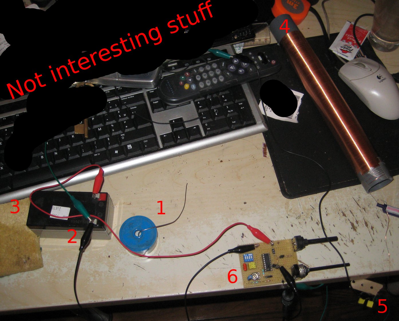
- Soldering wire. Not used
- Aligator clips. Needed. All the time. Many of them.
- 12V Battery
- Secondary coil (the L)
- Capacitor (the C = 100nF)
- FVG
I then just need to watch the voltage V accross the coil with my oscilloscope, and find the frequency for which the amplitude of V is maximum, which looks like this (but with less noise in the picture):
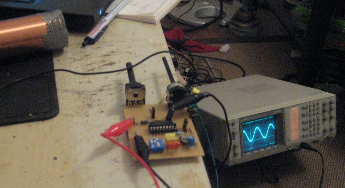
My oscilloscope is friendly enough to show me directly the frequency of the signal, given that I move 2 cursors around a full cycle of the signal.
Results time !
With a 100nF capacitor, I have a maximum at 10.4Khz, which gives me L = 2.4mH. That value is reasonable, and is somewhat coherent with another calculus I made with this page from Deepfriedneon website which gave me a theorical L=3mH.
Another part of a good tesla resonator is the topload. It’s the conductive torus you add on the top of the secondary coil which adds a capacitor load. I’m planning to test a few, from a tinfoiled lightbulb to tinfoil aeration conducts. Now I roughly know of the inductance of the coil, I can use the same schema to meseaure the capacitance of my toploads, and finally have an idea about the whole RLC circuit resonating frequency!
More to come!